Controls Engineering / Platform explainer
Ignition SCADA: visibility, control and the boundary between them.
A pump station makes SCADA easier to understand. The controller runs the local sequence. The operator needs a trustworthy view. Ignition connects those responsibilities—but the architecture determines what happens when the connection fails.
Illustrative engineering analysis. No Ignition installation or live utility was used for this article. The linked browser demonstration is a custom teaching model, not an Ignition application.
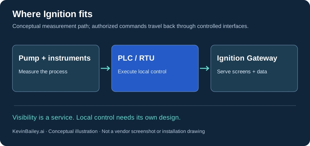
What Ignition brings to the control room
Ignition, from Inductive Automation, is a modular platform for industrial applications including SCADA and HMI. It supports equipment connectivity and technologies such as OPC UA, SQL and Python scripting, with MQTT integrations available. The functions you deploy depend on the selected modules and architecture. Read the vendor’s platform overview.
Gateway
The server-side foundation for connections, application services and configuration.
Designer
The development environment used to assemble the application.
Perspective
Browser-based visualization, including layouts for different screen sizes.
Vision
Desktop visualization for operator applications.
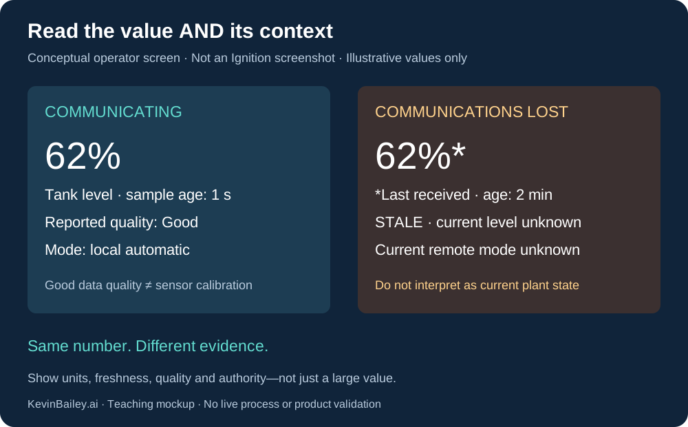
For a water utility, the useful outcome might be a consistent view of tank level, pump status, pressure, alarms and historical trends. Those displays need context: units, timestamps, quality and the current operating mode. A convincing screen is only useful if an operator can tell whether its information is current.
Follow one measurement through Ignition
Consider an imaginary pump station with a tank-level transmitter and a PLC. The following names and values are teaching examples, not a configured Ignition project or operating limits.
- Connect the device. Select a supported driver or OPC UA connection for the actual controller. Confirm addressing, trust and the permitted network path.
- Create the tags. Map a PLC value into an Ignition tag such as
PumpStation/TankLevelPct. Define units and scaling. Keep command and status tags distinct. - Build the display. In Designer, bind a Perspective or Vision component to the tag. Display the value alongside quality, sample time and operating mode.
- Add the alarm. Configure an engineered alarm condition, then its display, journal and any notification workflow. A threshold needs process justification.
- Record the trend. Configure the selected history system and retention. Verify timestamps, sampling and recovery against the actual application requirements.
Those steps explain the implementation path; they are not a substitute for the selected module’s configuration instructions. Ignition tags documentation.
The PLC and SCADA have different jobs
In the reference design used here, the PLC or RTU reads instruments and executes local control. Ignition provides supervision: operator visibility, history, alarms and authorized requests to change operation. This allocation is a design recommendation, not a guarantee that any installed system behaves that way.
A screen command should be a request processed through the approved control logic. Application permissions, controller interlocks, command feedback and the local/remote mode all need to agree. An on-screen button changing color is not sufficient evidence that equipment reached the intended state.
Good quality is information, not proof of a healthy instrument
Ignition quality codes express confidence in a tag value using Good, Bad, Error or Uncertain levels with more detailed codes. Its overlays help expose problems visually. A successfully communicated value can still originate from a drifting or stuck sensor: tag quality does not independently verify physical accuracy. Show units, timestamp, freshness and source diagnostics together. Quality codes and overlays.
Follow an alarm from detection to clearance
Imagine an engineered high-level condition becomes active. Ignition evaluates the configured tag alarm, the operator display presents it, and a separately configured notification pipeline may contact the on-call person. The alarm journal records events when configured. Acknowledgement records recognition; it does not repair the process or mean the condition cleared. Return to normal and acknowledgement are separate parts of the lifecycle. Ignition alarming documentation.
Test detection, display, journal recording, notification delivery and escalation separately. If email or another notification service fails, a functioning alarm screen does not prove the remote operator was reached. Process protection must follow the site’s engineered design.
Which connection disappeared?
| Failure | What may remain | What must be verified |
|---|---|---|
| Browser ↔ Gateway | Gateway collection and PLC control may continue. | Session disconnection indication; alternate operator access; command outcome if the session drops mid-request. |
| Gateway ↔ PLC / remote site | PLC local control follows its own programmed policy. | Bad or stale remote data, unavailable supervisory writes, local visibility and alarm arrangements. |
| Gateway ↔ database | Current display and device access may continue; supported writes may buffer. | History gaps, buffer capacity, journal behavior, database-dependent screens/scripts and recovery. |
| Active Gateway fails | Local PLC control may continue; a configured backup may assume Gateway duties. | Failover time, client reconnection, alarms, scripts and every shared dependency. |
Design for the moment the connection disappears
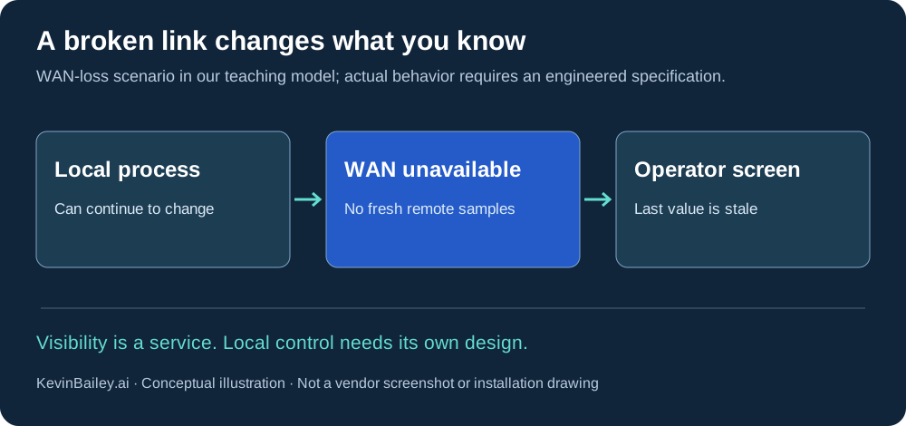
Our pump demonstration separates local model state from the last sample received by SCADA. During a communications outage, the local process can change while the remote display remains stale. That distinction is the lesson: loss of communications and loss of a local instrument are different faults.
Ignition’s store-and-forward facilities can buffer supported database-bound data in memory and on disk. They help systems such as Tag Historian and SQL Bridge handle database interruptions. They cannot recreate measurements that never reached the collecting system, and buffering is not a substitute for an alarm-delivery or local-control design. Capacity, retention and recovery need testing. Store-and-forward documentation.
Gateway redundancy addresses another failure class. Ignition supports a two-node redundant system, but a second server does not by itself remove shared power, network, database or field-device dependencies. Decide which failures the design must tolerate, then test them individually. Ignition redundancy documentation.
A useful bridge needs controlled crossings
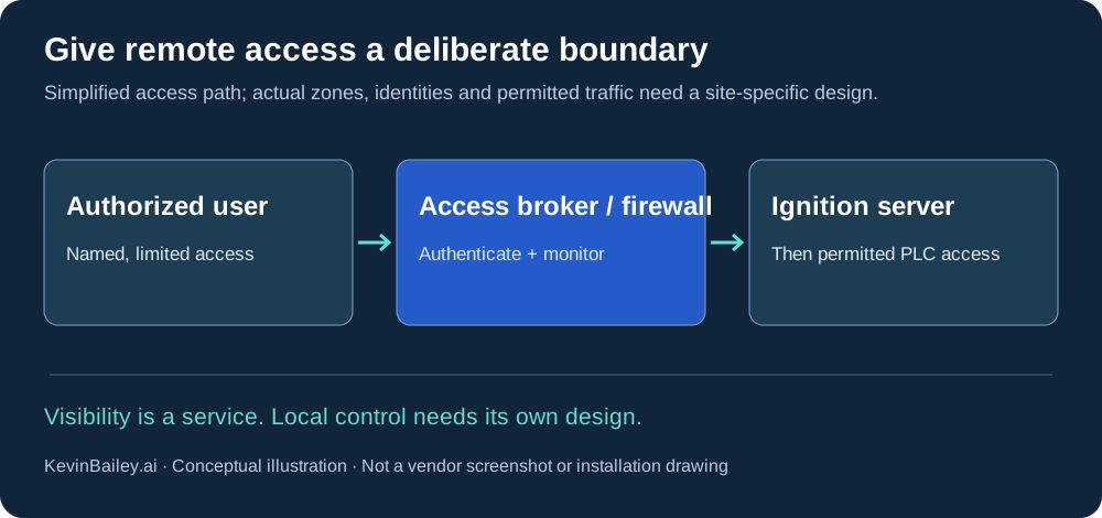
Inductive Automation recommends network segmentation and established security approaches such as ISA/IEC 62443 zones and conduits. Its guidance separates consumers of traffic: users, PLCs and databases should not all communicate directly with one another. Ignition security architecture guidance.
My recommendation for this example is to separate engineering administration, operator access and business reporting. Give each role only the access it needs. Route necessary remote support through an actively maintained boundary, and avoid direct public exposure of controller and administrative interfaces. A server connected to two networks should not be assumed to provide a security boundary simply because it has two network cards.
ISA/IEC 62443: what are zones and conduits?
ISA/IEC 62443 is a family of industrial automation and control system cybersecurity standards, covering organizations, systems and products. A zone groups physical or logical assets with common security requirements. A conduit groups communications channels between zones with shared security requirements. Zones are not simply VLANs, and a conduit is more than a cable: both express a security design that needs enforcement. IEC’s introductory explanation · ISA’s standards overview.
Apply it to the pump-station example
Candidate zones might separate corporate reporting, remote-access services, Ignition supervision and field control. The final grouping follows the risk assessment—not a universal network diagram. A reporting conduit might allow a defined data service while denying direct business-user access to PLC programming. A support conduit might allow an approved engineering session through the access broker, with a named owner and recorded activity. These are illustrative design choices, not proof of conformity.
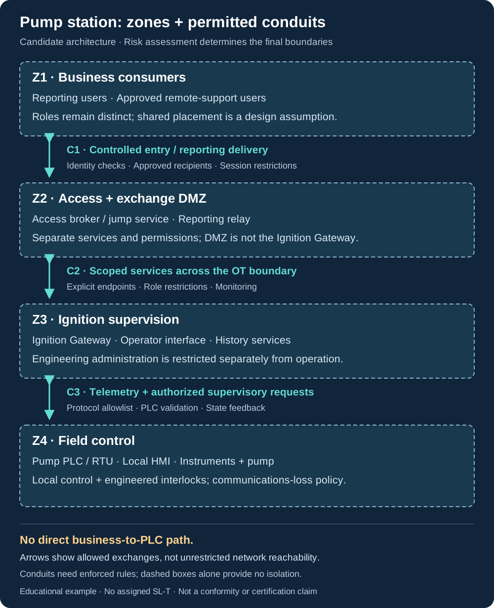
Read the conduits as requirements, not open pipes. C1 admits approved support sessions or delivers reporting through the designated DMZ services. C2 permits those services to reach only specified supervisory endpoints; reporting is read-only and support privileges require separate authorization. C3 carries defined telemetry and permitted supervisory requests between Ignition and the PLC/RTU, with controller-side validation and feedback. PLC programming access is outside this illustrated path and needs its own assessed, explicitly authorized conduit if required.
Design assumptions: this simplified view groups business consumers together and groups supervisory/history services together. Risk assessment may split them into more zones. Real designs must also inventory local engineering access, vendor links, wireless/cellular paths and external dependencies; a line omitted here is not proof that no such connection exists. Specify endpoints, protocols, initiators, owners and enforcement for each actual conduit.
What does meeting the applicable requirements entail?
- Define the scope and risk. Identify the system under consideration, assets, dependencies and consequences. Partition it into zones and conduits, assess each and establish justified target security levels (SL-T). Record the security requirements. This is the focus of IEC 62443-3-2:2020.
- Specify and implement the controls. Map applicable system requirements to the target levels. IEC 62443-3-3:2013 addresses identification/authentication, use control, system integrity, data confidentiality, restricted data flow, timely response to events and resource availability. A firewall addresses only part of this work.
- Operate a security program. The asset owner needs policies, responsibilities and procedures across the operational lifecycle. IEC 62443-2-1:2024 addresses that program; other parts apply to service providers, product development and components. Select the relevant parts and editions for the role and scope.
- Produce evidence and assess gaps. For this example, prepare a requirements-to-evidence register: zone inventory, allowed-flow matrix, access rules, configurations, test results, backup/restore evidence and responsible owners. Evaluate applicable clauses and unresolved gaps against the authoritative standards. Record the limits of any conformity claim and maintain evidence as the system changes.
A target is not an achieved result. SL-T describes the security sought; it does not prove that deployed controls deliver it. Security levels are not interchangeable with organizational process maturity. Buying a certified product, drawing zones or installing Ignition does not establish that an entire plant conforms.
Educational summary, not a conformity assessment. Meeting the standard requires evaluation against the applicable normative text, defined scope and editions. A formal certification claim additionally needs the relevant certification scheme and assessment. This article and the pump demo have not been assessed or certified to ISA/IEC 62443.
Restore the system, not just the project
A project export and a Gateway backup have different scope. Gateway backups capture projects and Gateway configuration, including connections and alarm settings; a saved database connection is not a backup of the external database itself. Maintain separate recovery plans for external history and journals, PLC programs, certificates and identity/network dependencies. Check the backup scope for the installed version. Gateway backup and restore.
Assign owners: controls maintains controller logic and application behavior; IT maintains the agreed server, identity and database services; operations witnesses restored visibility and authority. In an isolated environment, restore a version-identified backup, validate dependencies, and record recovery time and acceptable data loss. Redundancy does not replace this restoration exercise.
Before choosing Ignition
- Equipment fit: confirm exact controller families, firmware, protocols and driver support.
- Application fit: choose visualization, history, reporting and notification capabilities deliberately; identify any third-party modules.
- Capacity: define tag rates, sessions, history retention and expected growth; size and load-test the architecture.
- Ownership and cost: account for licenses, support, engineering, database/OS services, backups, patching and training—not just the first software purchase. Obtain a current scoped quote.
Perspective and Vision are application choices; a browser interface does not require exposing the system publicly. Start with the operator’s task and the access design. Platform and module overview.
What I would demonstrate before accepting the design
- Normal operation: values, quality, timestamps, commands and feedback agree with the simulated process.
- Communications loss: stale information is unmistakable and the documented local response occurs.
- Separate failures: test instrument faults, Gateway failure and database interruption independently.
- Recovery: fresh state and authority are reconciled before supervisory commands resume; obsolete requests do not unexpectedly actuate equipment.
- Access and restoration: verify role restrictions and restoration from known backups in an isolated test environment.
These are proposed acceptance topics. No installation testing or plant acceptance has been performed for this article. Actual limits, fallback behavior and test procedures belong to the responsible operations and engineering teams.
Check your understanding
The screen says 62%. The sample is two minutes old. Is the tank still at 62%?
You cannot tell from that screen. It reports the last received value; establish approved current visibility rather than treating it as present process state.
The alarm was acknowledged. Has the high-level condition cleared?
No conclusion follows from acknowledgement alone. Inspect the condition and its return-to-normal state.
A Gateway backup restored successfully. Is historical data recovered too?
Not necessarily. Validate the external database and other separately managed dependencies against the recovery plan.
Try the pump-station teaching model → · Read the water utility architecture →